Combined
Handout for
Basic
Blacksmithing
Practical
Blacksmithing
And
Forge
Welding
Taught
By
Scott B. Jaqua
7082 Kermore Ln.
Stanton, CA 90680
(714) 761-7114
Table of
Contents
About the use of
non-period tools
Appendix 'A' Forge Construction
"Modern
materials, techniques, etc. are allowed if they produce a period effect."
(Page 11, of the rule booklet for the 2001 Caidan Arts Pentathlon)
Introduction
The purpose of these classes is to give the student an introduction and the basis for further exploration of the art of blacksmithing. This document is designed to serve as an auxiliary for all three classes, rather then as a single set of class notes. It is suggested that the student make careful notes of their observations of class demos. Because, many are the blacksmithing skills that can only be learned by seeing or feeling the process yourself.
About the use of non-period tools
During this class we will be using some modern tools. However the actual skills with hammer and anvil hasn’t changed in centuries. I use a propane forge in place of a more period coal or charcoal forge for three reasons. The first has to do with my home shop environment. The propane forge burns much cleaner, especially at startup. This is very important in allowing me to work out of my home. It keeps the Air Quality Management District off my back and it keeps my neighbors happy. Propane is also cheaper for me to run. And last, propane eliminates the task of fire maintenance that takes up almost half of a blacksmiths time when using coal. However propane also has drawbacks. The major one being that you can’t spot heat something the way a properly built coal fire can.
Also in this class you will see me use a belt grinder. The period process would use a grinding stone and files. However the use of the power-tool will allow us to actually finish projects in the allotted time.
Safety
These classes involve the use of tools and techniques that present a number of safety concerns. The foremost amongst these are fire and burns. So while we will discuss safety in the each of the classes please also review these safety rules.
Always wear safety glasses.
Wear leather gloves, especially when welding or grinding.
Wear an apron a leather apron is best.
Wear close-toed leather shoes while working in the shop.
Wear only natural fibers.
“If it’s falling let it drop”
“Of you’re not sure, it’s hot!”
No horseplay in the shop.
Always know where the exit and the fire extinguisher are.
Make sure you are working in a well-ventilated area.
Basic Blacksmithing
Blacksmithing is the art of moving hot iron under the hammer. It is named blacksmithing because you are working with black metal. This is due to the formation of black iron oxide during the forging process.
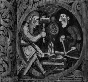
Blacksmithing dates back to the very beginning of the Iron Age. And it is a direct descendent of the bronze smith. If you were lucky enough to see the Smithsonian’s traveling exhibit, “The North Atlantic Saga”, then you could see the very early blacksmith and foundry tools found at Viking dig sites. Since that time, only minor changes have been made to the basic form of the blacksmith’s tools.
The best way I have found to explain the smithing process is to say that when iron is heated enough it becomes plastic like. If you can form the object by squeezing clay, then you can form it from hot steel by shaping it with a hammer.
In the Basic Class we will learn basic skills. We will cover the blacksmith’s tools and their uses. The skills learned will include flattening, tapering, drawing upsetting and hot cutting steel. And if time permits the entire class will work on a simple group project.
Tools
The Basic tools used by blacksmiths have not changed in hundreds of years. At it’s most basic level, beside a forge, the smith needs something to hold the work, something to strike the work and something to strike it against. Almost all blacksmith tools fall into these three categories. This class will cover some of the basic tools that I use. This is only a relatively small sample of the types of tools used. Each blacksmith specialty uses it own sort of special tools. The tools I have are of a general nature along with a few used by bladesmiths. During the three classes we will use the following tools.
Forge (construction details of which may be found in Appendix ‘A’)
Anvil
“Post” or “Leg” Vise
Tongs (different shape jaws to hold different shaped work for different jobs)
Scroll Pliers
End Cutters
Diagonal Cutters
Cross Peen Hammer (this is the most used hammer)
Straight Peen Hammer (best for drawing operations)
Ball Peen Hammer (used for raising and sinking operations, also used for peening a rivet)
Single Jack (heavy hammer for moving a lot of metal, fast)
Hammer Chisel
Flatter
Hot Cut Hardy Tool
Cold Cut Hardy Tool
Fuller Hardy Tool
Swage Block
Twisting Tool
Wire Brush(s)
Flattening
Flattening steel is self-explanatory. Simply place the heated work flat on the anvil and strike straight down with the hammer. Now using our clay analogy above, you should be able to figure out what would happen by placing a piece of clay on the table and hitting it with your hand. The piece will be reduced in height while increasing in length and width. However there is another aspect of flattening. And that is the removal of hammer marks. Now if you are really good, you didn’t leave hammer marks. But I’m not that good. To that end during class I will show you how to use the flatter.
Tapering
Tapering iron/steel is almost self-explanatory. First bring
the work up to working temperature in the forge. You will want to work in a
bright red color range (this is one of those see/feel things). Then take your
piece to the anvil, working
near the anvil edge. Line up the work piece edge with the table edge. Then lift
the back of the work and also bring the hammer face in at an angle along the
work and anvil edge. The angle on the hammer face is twice that of angle from
the work to the anvil. So as you form the taper, you will increase the angle on
both the work and the hammer. Use caution in that you hit the work and not the
anvil. Working near the edge of the anvil will lessen but not eliminate that
risk.
Drawing
Drawing is the technique used to lengthen and reduce the height of the work without increasing the width. The best tool to do this is a straight peen hammer. On the first heat, using the peen of the hammer, place a series of groves across the length of the piece.

On the next heat, use the hammer face to flatten the groves. This will reduce the height and lengthen the piece while increasing the width ever so slightly.

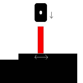
Upsetting
Upsetting is used to shorten the work (rod or bar stock) while increasing the height and width. You can either hold the heated end of the work against the anvil face and strike the other end with a hammer or you can clamp the work in the vice and strike the heated end directly.
 or
or 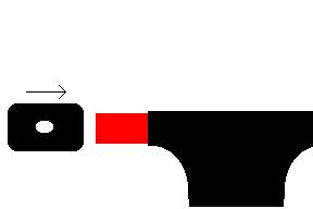
Hot Cutting
Hot Cutting is done using a chisel or a hot cut hardy tool. With either tool, care must be taken to not scar the anvil or the hammer face. When using a chisel, do not cut on the anvil face. Use either the cutting pad of the anvile or place a cutting plate over the anvil face. With both tools you want to cut a little over ¾ of the way through the piece and then turn it over to complete the cut.
 or
or 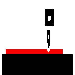
Now, besides these techniques there is any number of other ways to move metal under the hammer. The way in which you strike the blow and the shape of your tool are what controls how the metal move. In the next class you will be introduced to new tools and techniques that will build on the skills learned here.
Practical Blacksmithing
Spoon Project
In this class we will apply what we learned in the last class to make something from start to finish. That something will be a spoon. But prior to starting the project we will do a brief review with an emphasis on safety.
Material
For this project we will use ½” 1018 steel bar stock. 1018 steel is a low carbon steel that will work not that much differently then period wrought iron. The first step in the project is the cut our steel to length. Now if I were a period smith working in my own shop, I might leave the bar full length and cut the spoon off the end of the bar once I was done. But as we have two bars and four students we will cut the bars in half, using the hot cut hardy.
Cutting
You hot cut steel in order to preserve material. Sawing removes a small amount of the metal as part of the saw curf. Also hot cutting is faster then cutting the metal using a hand saw. For both these reasons, period smiths would hot cut their iron stock. For this project cut the supplied bars in half.
Upsetting
Next we want to upset one end of the bar. This is to insure we have enough material for form the bowl of the spoon later. We want to upset the bar so that the last inch is between 5/8 and ¾ inch wide.
Flatten
Next we will flatten our bar to reduce it’s height to about ¼ inch. This will lengthen the bar a little, and make it wider. It should be about ¾ inch wide when we are done, a little wider where we upset it.
Drawing
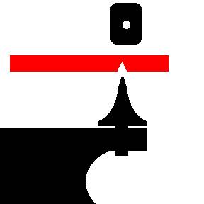
The next step is to draw down the handle. We want to form the handle in the center of the bar’s width. See the illustrations below to see how this is done.

(1) (2) (3)
Step 4 is a repeat of step 2 on the other side. Make sure you start you handle below the portion of the bar that you upset.
Forming the bowl
To for the bowl you first need to further thin and widen the upset end of the bar. Do this by using the peen of a cross peen hammer to put in grooves running the length of the bowl. Then use the hammer face to flatten the grooves. Repeat this as need, being sure to work only one side of the piece. We want to lower the bowl in relation to the handle. Once the bowl portion is about 3/32” thick, we need to go to the swage block. Using the peen of the ball-peen hammer sink the bowl into the smaller spoon die.
Finishing the handle
Once the bowl is formed, it’s time to finish the handle. For this project we will twist the handle and add a scrollwork detail to the end. Prior to twisting the handle, we’ll save a great deal of work later if we rough grind the handle now. Once the handle is ground good and square we will twist a section of the handle. To do this heat the spoons handle and then clamp the last inch of the handle in the vise. Using the twisting tool grab the handle about an inch below the bowl and start twisting. Don’t force the twist, if you do, you risk cracking the steel. Reheat and continue twisting as needed. Be sure you finish at an even ½ twist. Take the spoon out of the vise, reheat and taper the handle end down like a screwdriver, in the same plane as a spoon bowl. Take one last heat on the handle end and use the scroll pliers to roll the end over.
That’s it! Now you just need to take a lot of time to hand polish your spoon or a little less time to polish it using a Dremel tool.
Forge Welding
Forge welding is a basic blacksmithing technique. It is one that allows the smith use all his scrap metal, allowing none to go to waste. It also allows for the smith to build larger more complex pieces. And last it can be used to combine steel of different properties into the same piece. In this class we will try our hand at forge welding. We will do some basic welds on scrap metal, make some welded cable and maybe attempt some pattern welding.
Forge welding is done by taking two pieces of steel to the correct temperature and pressing the two pieces together via hammer blows. However a lot of things can prevent a good weld from happening. Part of the secret of a good weld is having the correct temperature throughout the entire weld area. This can only be taught, by watching it being done.
The basic welding process
The first step is to have well meeting clean surfaces. Forging them to shape and brushing the scale off can form these surfaces. But cleaning up the surfaces with a grinder might fix a lot of headaches.
Next you want to make sure your pieces don’t move while you are trying to weld them. This can be done by having someone hold one or both pieces for you. But many smiths are working solo; so wiring the pieces together is what is done more commonly. When welding carbon steels, using stainless steel wire, will mean the wire doesn’t get welded to the work. Because; stainless steel welds at a much higher temperature then carbon steel.
Take your wired piece to the forge and heat them to a nice shade of red. Then take the pieces out of the fire and flux them. Flux serves two purposes. The first is the further clean the surfaces to be welded. The second is the seal the steel off from the atmosphere, and prevent oxidation from forming in your weld. The most basic forge welding flux is anhydrous borax. At a read heat, the flux should melt and seal the surface. And molten borax is corrosive, and will etch the steel surfaces clean.
Now take you fluxed pieces and return them to the fire to bring them up to welding heat. This heat varies with the steels and flux used. But a general guide line is wait till the flux starts to bubble. Then wait till the bubbles start to “dance” over your work. And then wait some more to make sure the entire piece is at welding heat (this is called soaking the piece).
Once you at welding heat, quickly take the work from the fire, to your anvil and strike it with your hammer to set the weld. “Strike while the iron is hot” means exactly that. Depending on the size of your work, you will have anywhere from 10 to 20 seconds at welding heat. When you are hammering the weld, you don’t need to hit it too hard. What’s too hard, only experience will tell you. But in general, let the hammer do the work. Hit the piece too hard and you risk squirting out molten steel along with the flux and slag that normally squirt out. Speaking of that flux and slag, watch out when you are welding. Make sure you don’t hit someone or something with the molten flux/slag mess that squirts out.
Welded Cable
Preparing The Cable
The first step is to get some cable. It's important here to talk about cable or "wire rope". You want a high carbon steel cable. You want to make sure it is all steel and doesn't have a rope or vinyl core that will just make a mess in your forge. Good cables to use are "improved plow share" cable or "extra improved plow share" cable. If you get your cable from the scrap yard, you want used heavy lifting cable. Salvaged crane or elevator cable in 3/4 inch up to 1 1/4 inch diameters are good to work with.
Once you have your cable, now you need to prepare it for use. The first step is
to cut it to a workable length. My forge has a nine-inch long chamber, so I
work with six or seven inch long sections. To cut the cable, I use a chop saw
with a metal cutting blade. Now the cable I am using currently tends to resist
coming apart, but some cables will fray when you cut them. To cut these cables
you will want to wire the cable together on both sides of the area to be cut. 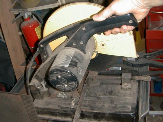
Once the cable is cut, some makers recommend cleaning the cable. While I have not had any problems welding the cable I have, others have reported problems with the preservatives on the cable. This preservative is made up of oil/grease and an asphalt like material.
There are two ways to clean the cable that I know of. The first is to make a super saturated borax and water solution. Then heat the cable to a dull cherry and quench the cable in the borax solution. This will burn off some of the preservative and blast the rest off with any slag. It also lightly coats the wire strands in flux.
The other method of cleaning the cable is to use a solvent. For this method you need to take the cable apart into its wire bundles. Once it's apart you need to use gasoline and a stiff brush to scrub the wire bundle down. Be sure to do this in a very well ventilated area, away from any flames. Also you will want to use a solvent safe, plastic or rubber tub. You don’t want to take a chance of the wire cable or wire brush causing a spark from hitting a metal tub. Taking this cleaning operation outside the shop would be best. Once the wire bundles area clean, it's time to reassemble the cable.
Next you need to wire the cable ends, if they aren't still wired from when you cut it. For this step I like to use stainless steel wire. Stainless steel welds at a much higher temp then high carbon steel. So after you weld the cable ends, you should be able to just cut the stainless steel wire loose from the billet. You wire the cable ends to prevent them from separating as you first weld the ends.
So now you have a cut (cleaned?) and wired piece of cable ready to weld. But
what if you want to dress up the welded cable some?
Adding Nickel To Welded Cable
Damascus, or pattern-welded steel, gets it beauty via etching. When you etch pattern-welded steel, you get contrast between the different bands of steel (either due to different carbon content, or different alloying elements in the two steels). Welded cable is all the same steel. So how do you get a pattern? Most makers believe it is due to a slight difference in carbon loss where the strands are welded together. However, this only tends to produce a little contrast into the finished product.
One of ways to dress up an item made of welded cable, is to add nickel to the mix. Nickel will forge weld to steel just fine (but not to another piece of nickel). When you wrap nickel around alternating wire bundles that make up a cable, the finale product will be speckled with bright spots in the scale like pattern that welded cable produces.
Most knife makers and other smiths, use strips cut from thin nickel sheets or thin nickel wire. I was having a hard time locating a local supply of nickel, so I had to use 3/32 "nickel 99", arc welding rod, from the welding supply store. To use this material I first had to break off the flux coating on the rod. I did this by lightly striking the rod with a hammer on my anvil. I used a wire brush to finish getting the flux coating off.
Once the flux was off the rod, I then forged the rod down to a thin sheet in my
propane forge. After I forged the sheet out and let it cool, I split the sheet
even smaller by cutting down its length with tin snips. 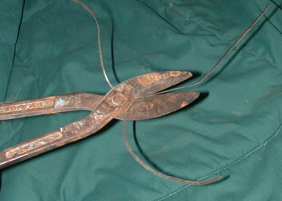
I
then took my cable piece apart into its wire bundles. The cable I am using has
seven bundles. Six bundles are wrapped around a seventh core bundle. Because
nickel won't weld to nickel, I wrapped every-other one of the out side bundles.
That way there is no way the nickel will touch nickel during welding. I then
reassembled the cable piece as best as I could and wired the ends tight to hold
it all together. 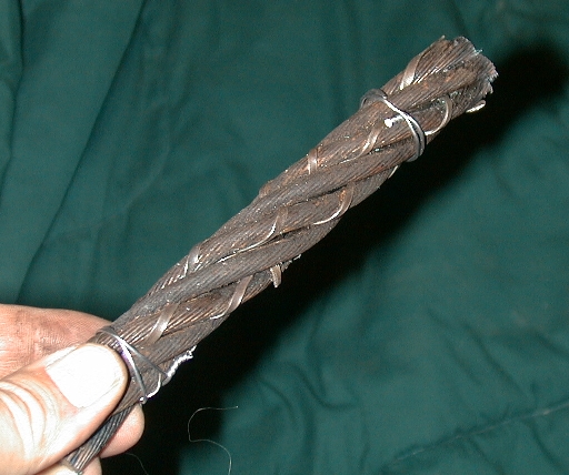
Welding the Cable
The first welding course
Now
that you have prepared the piece of cable, it's time to weld it. These
instructions will assume you are using a gas forge, like I do. If you use a
coal forge, these instructions will still work, with minor changes. The first
step is to weld the two ends. Use the same procedure on both ends.
Start your forge and a let it come up to a welding heat.
Stick the cable into the forge, leaving one end sticking out for your tongs to
grab. Try to only heat the end you are working on. The fewer heats that any
portion of the cable receives, the better.
Once the cable end is nice and red (as seen under shop
light, not day light), take it out and add flux. For flux I use plain Anhydrous
Borax. Other smiths may use other "mixes" but I find the Borax does a
good job without introducing any "crap" into the weld. When adding
the flux it is not possible to over flux the piece. However, too much creates a
mess in your forge and any that comes off the piece will eat your forge lining.
Sprinkle the flux on until a light powder coating sticks to the cable. Once
that melts in the forge, you should see a thin "wet" coating
on all the wires.
Once the piece is fluxed, return it to the forge. You now
need to heat the piece to a welding temp. Cable welds in the yellow color
range. But color is hard to gauge in all lighting situations. So watch the
flux. Wait for the flux to bubble, then watch for the bubbles to "dance"
over the surface of the cable. Now wait a touch more, to make sure you are at
the same heat all the way through the cable.
Quickly use your tongs to take your cable from the forge to
the anvil, you only have a little bit of time to work at a welding heat ("strike
while the iron is hot" means exactly that to the would be smith). Lightly
strike the end with a 2 or 3 pound or hammer. Let the weight of the hammer do
the work. Turn the cable between blows; you always want to work the cable round
while welding. (Note; welding the cable in the half round grooves of a
swage-block will help a great deal and is almost required to get good welds on
larger diameter cables.) As you hit the cable you should be able to feel the
weld take, back through the hammer handle. If the weld sticks, you will feel
some resistance. If the cable is too cold you will just feel the end of the
cable mush. As more and more of the cable welds, you will feel more and more of
the blows energy came back through the handle. In one heat you should be able
to weld about one inch of length on a 3/4" cable.
Once you reach a red heat, stop hitting the piece. Now use
your wire brush to remove any scale from the welded section. So long as you are
at red heat the scale should brush right off. Any cooler and the scale will not
come loose. If you didn't get the end completely welded, reflux the end and
return it to the forge. Repeat the last steps until the end of the cable is
completely welded all the way around.
Put the cable down on your anvil and let go with the tongs.
Now grasp the cable, with the tongs by the end you just welded. Return the
cable to the forge sticking the un-welded end into the forge (don't forget to
cool your tongs, by dunking the jaws in your slack bucket). Repeat the heating,
fluxing and welding steps above until both ends are completely welded.
Once the ends are welded, it's time for a little twisting to
tighten up the pattern and make welding a little easier. Put the entire piece
of cable in the forge. Heat the cable until it is in the red color range. Take
the cable out and lightly flux the entire length. Put the cable back in the
forge and bring it up to a yellow heat. Take the cable out and quickly clamp
one end in the vise and twist the other end with a special wrench or Visegrips.
During this twisting some strands may actually weld. Some scale will also flake
off during the twisting; so don't stand too close to the vise (scale may look
black and cool, but don't let that fool you, it's hot!). Don't twist so hard that
you shear the piece (you will feel any strands break).
Take the cable from the vise and lightly wire brush it. Then
pick an end and flux it for about an inch above the welded end section. Return
it to the forge, putting the fluxed end into the fire. Repeat the steps above
for welding the ends on this section of cable. Repeat as needed to weld the
whole billet. Once your weld reaches the center of the cable turn it around,
but keep the weld working down the cable in the same direction (so that you finish
at the opposite end of the cable from where you started).
That completes the first course of welding.
The Second Welding Course
You
run the billet through a second welding course to make sure it's welded,
tighten up the pattern and clean up the billet surface.
After the billet is wire brushed from the final weld above,
lightly flux the entire thing. Return the billet to the forge and bring it up
to a welding heat. Take the billet out of the forge and quickly clamp one end
in your vise. Grab the other end with you twisting wrench or Visegrips. Twist
the billet as tightly as you can without shearing any welds (this may take more
then one heat). After you twist the billet take it out of your vise, wire brush
it and lightly flux it again. Return the billet to the forge.
When the billet reaches welding heat (watch for the boiling
flux to "dance" over the piece), take it out and work and inch or two
length with firm hammer blows while turning the piece. Only work the metal
while it's at welding heat. Once the billet drops into the red color range,
stop striking it with the hammer (the hardest thing to do is resist taking just
one more blow). Wire brush while the billet is in the red range, reflux
it and return it to the forge. Repeat as need until you have run the second
weld course over the entire length of the billet.
A Note On Welding Time
The two welding courses must be finished as quickly as possible. This is to prevent carbon migration as much as possible. This is very important to the pattern development of welded cable. Welded cable derives its pattern solely from differences in carbon content. And that difference is caused decarbonization of the welds. Now if the billet is kept too hot for too long, carbon will tend to move back from the high carbon strands into the lower carbon welds. Thus blurring your pattern.
Pattern Welding
Entire books have been written on the subject of pattern welding. While we may attempt a simple pattern weld in class, it is not the purpose of this document to cover the topic in depth. For that I would direct the reader to Master Atar’s book, The Pattern Welded Blade. However, if class time remains we will attempt to create a simple pattern welded billet. So to that end, these instructions are provided.
For the class project, we will be making a low layer count, star twist pattern. We are using this because we will not have time to drawn down the billet and weld it back on it’s self, to increase the layer count. Ad a twist is the fastest way to manipulate the layers to produce a pattern.
Materials
For this project we will be using 1/8” x 1” strips of 1084 and 15N20. These two steels are both middle to high carbon steels, and even with a low layer count will make a well performing knife blade. We will get the contrast in our pattern from the Nickel content of the 15N20. These materials were also chosen because of the relatively similar carbon contents. This will prevent carbon migration from blurring our pattern.
Prep Work
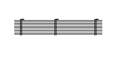
In order to save class time, some prep work has already been done to our materials. Four pieces of 1084 and five pieces of 15N20 have been cut to a length of six inches. These pieces have then been taken to the grinder, to have the mill scale removed. The pieces are then stacked starting with the 15N20 layers on the outside. Last, the resulting stack is wired together, just like we did for the cable, however; in this case we will wire it in three places (this is very important, as we do not want our stack sliding around during welding).
Welding a Multi Layer Billet.
We begin by placing one end of our billet in the forge. Once all the pieces reach a red heat (check the middle sections by looking end on), we add flux as we did while welding cable. Sprinkle on a like flux and return it to the fire. After a little while pull it out and check to see if you need to add more flux. If we added just a little, before. And if capillary action has pulled the flux in between the layers, like it’s supposed to, then we will need to add a light dusting of flux to completely seal our layers from the air.
Return the billet to the fire again and wait for it to come up to welding heat. Visually make sure all the layers are welding heat and not just the outer layers. Take the billet from the fire and quickly place it on your anvil face and strike it with you hammer to set the weld. Warning; welding multiple layers for a pattern-welded billet will cause molten flux and slag to squirt out more and further then any other welding operation! Make sure your area is clear of people or flammable objects, prior to welding! Work the first inch or so of the bar with you hammer, until you are no longer at welding heat. Then check the weld area while the bar cools slightly. If the weld area maintains an even color while it cools, then its welded. If you see any stripes that are a different color within the welded area, then you have an un-welded layer. Wire brush the area, reflux it, return it to the fire and work the weld area again if need be. You must have the end solidly welded before continuing on. Once the end is welded, cut off and remove the wire. Wire brush the scale off the billet, turn the piece on the anvil and repeat the process for the other end. Complete the welding course just like we did for the cable. And run a second course of welding just to be sure we got all the layers welded together. Because we are about to test those welds to the extreme.
Patterning the Bar
Once all your welds are complete, it is time to pattern the bar. To do this we are going the take the entire bar to almost a welding heat and then twist it in the vise. If any of our welds are not good, they will shear during this process. In order to completely twist the bar, we will need to take several heats. And in order to keep an even twist, we will want to turn the bar over, every heat. On our six-inch bar we will try for two or three full turns, which will give us four to six stars in our pattern. Once the bar is twisted, the last steps are to flatten it back out and then draw the bar down to our desired thickness.
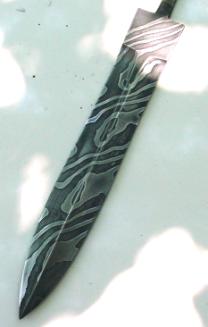
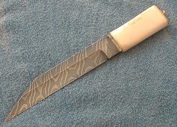
Developing the Pattern
To show our finished pattern, we would need to grind our surfaces smooth and then lightly etch the bar in either ferric chloride or vinegar. The 15N20 layers will stay bright, due to the Nickel content, while the 1084 layers will turn dark.
Appendix 'A' Forge Construction
One of the things my shop has always lacked is a forge. Until now, I have always formed metal using my collection of torches. Then I found Ron Reil’s web page about building your own forge and forge burners. At that point I decided I was tired of making do with torches. So the plan is for this page to document the construction of my forge.
Warning: The construction and use
of a forge is dangerous. Anyone building a forge based on what I have written
here, does so at his or her own risk. This page is provided for information
only and is not to suggest that you build your own forge. This forge is
experimental and not a proven design. If you decide to build or use a forge,
please make sure you have a complete set of safety equipment for the tools you
use.
The Overall Plan: The first step was to decide on the size of chamber I needed. This is dictated by the size of the work you want to do. The chamber size dictates the number and size of burners, you will need. Now, most of the work I'm planning on doing is flat and wide. I also plan on doing some knife work at some point. So as a starting point for my forge design, I looked at Master Atar's "nuclear toaster” blade forge, as shown on his video. From there, I decide to widen the forge chamber to handle the large rings I use in my hilt designs. Lastly, I shortened the height of the chamber to keep the total volume down. The resulting chamber size allows me to use two firebricks as a floor. Overall the end product is going to look like a cross between a blade maker’s forge and a farrier’s hotbox forge.
Materials List
For the two Forge Burners and Supply Lines
(2) Pre-made Burner Flairs (from Larry Zoeller)
(2) 1 1/2" to 3/4" Reducer Bells (this and the next several items can
be found at most plumbing supply outlets)
(2) 3/4"x 8" Pipe Nipples
(2) 1/8"x4" Pipe Nipples
(2) 1/8" Pipe Caps
(1) 1 1/2"x3" Pipe Nipple
(1) 1/8" Pipe "T"
(2) 1/8" Ball Valve
(2) 1/8" 90deg Elbow Fittings
(2) 1.8" 60deg Elbow Fittings
(2) 1/8"x1" Pipe Nipples
(2) 1/8"x1/2" Pipe Nipples
(1) 1/4" to 1/8" Adapter
(1) Propane/Gas Hose
(1) Goss Propane Regulator (found at most welding supply stores)
For the Axial Choke Assemblies
(1) 5/16" All Thread Rod (you will need about a 6"
length)
(4) 5/16"x3/4" Hex Bolts
(2) 5/16" Lock Washers
(2) 5/16"x1 1/2" Fender Washers
(2) 5/16" Hex Nuts
(2) 5/16" Junction Nuts
For the body and forge chamber
(2) Fire Bricks
(10 sq ft) Kaowool Fiber Blanket
(1 pint) ITC 100 Refractory Coating (This and the other two items above can be
found at the Clay Art Center)
(2) 3/4x1/8 Angle Iron, 4 feet long
(2) 2x1/8 Angle Iron, 4 feet long
(1) 3/4x1/8 Steel Bar Stock
(1) 1 1/2"x10" Pipe Nipple
(12) 1/4x20x3/4 Thumb Screws
(2) 3 Inch Hinges
(50) 3/16x1/4 Pop-Rivets
(1 sq ft) 16 Gauge Sheet Metal
(5 sq ft) 22 Gauge Sheet Metal
(1) 3/4x1/8 Square Tube Stock, 3 feet long
(2) Cans Zynolite, Black, High Temperature Spray Paint
The Forge Burners
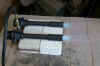
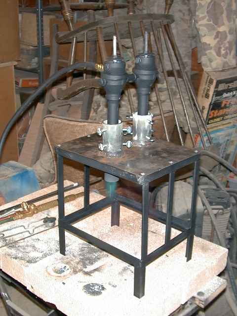
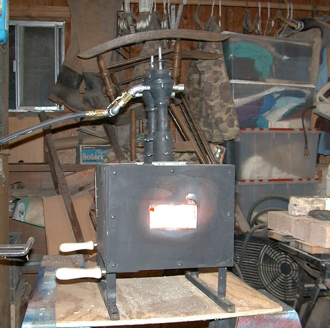
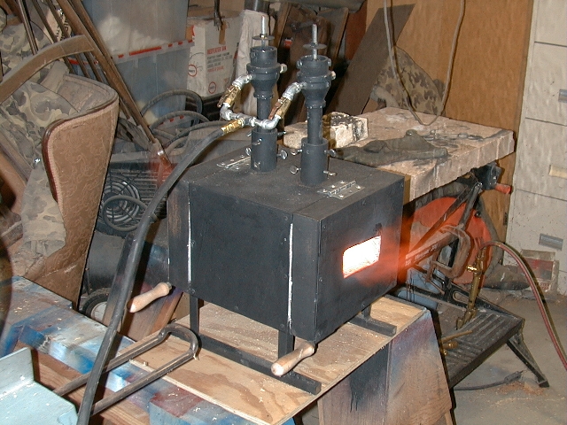
The first step is the construction of the forge burners. I used the EZ Burner plans found on Ron Reil's web site. Using the calculations on Ron's page, I determined I would need two burners to insure my forge can reach a welding heat. For burner construction details please see the attached plans. I modified the plans slightly, in that I secured the 1/8" pipe that is the gas jet, by using half of a 1 1/2"x3" pipe nipple. First I cut the nipple in half and then screwed the two halves into the backs of the reducing bells, to lock down the 1/8" pipe. By using the 1 1/2" pipe, I allowed for the future addition of an axial choke as shown on Ron's site. The two finished burners were then joined by a "T" fitting. Next a brass ball valve was added. The propane line was attached using a 1/8" to 1/4" adapter. For a propane regulator, I used one made by Goss and purchased from a welding supply store. Below you can see photos of the burners being test fired. The first photo shows the burners running at 4 P.S.I. of propane, the second is at 28 P.S.I. The second photo shows that the direction of the gas jets still needs to be adjusted so that they point straight down the burner tubes.
![]()
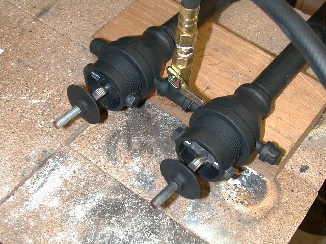
The next step is to add a choke. The choke will let me adjust the airflow so as to maintain a clean neutral flame in the forge no matter what gas pressure is used. I decided to use an axial choke based on what I had seen on Ron Reil's page. The choke I built uses elements from an axial choke seen on the site.
First I marked the section of 1 1/2" pipe that locks down the 1/8" gas jet pipe. I marked the 1 1/2" pipe where it lined up with the gas jet pipe. Using these marks, I drilled a pair of holes thru each 1 1/2" section that will run parallel to the gas jet. Next, I cut two 3" sections of the 5/16" all thread. The all thread was then brazed to the junction nuts at a 90 degree angle. Using two 5/16" bolts and one lock washer per burner, the all thread/junction nut assembly is fasten inside the 1 1/2" pipe sections to act as an upright. Last the two 5/15" nuts are brazed onto the fender washers to act as choke plates. These threaded plates are then turned down onto the all thread. Last, the 1 1/2" pipe sections are returned to the their task of locking down the gas jets. Below is a close up of the completed chokes.
The final operation to be performed on the burners is to tune them. Ron Reil has complete tuning instructions on his forge burner FAQ page. To tune my burners, I first increased the gas jet holes from .0400" (#60 drill bit) to .0420" (#58 drill bit) . (Note: after testing the completed forge, I went back and replaced the 1/8" pipe and returned to a .0400" gas jet hole. The why of this will be explained later.) Next, I had to adjust the gas jets to point straight down the burner tubes. Last, I adjusted the burner flair to 1 1/8" of exposure from the end of the 3/4" burner tube.
Building The Forge Box
The forge box is built around a solid floor of two firebricks, two inches tall. Now firebrick is not as good a refectory material as Kaowool. So the firebrick will sit on one inch of Kaowool. I want the forge chamber to be three inches high. The Roof will have two inches of Kaowool. So the total height of forge box will be 8 inches. The box length will match that of the firebricks at 9 inches. I want a 7-inch wide forge chamber with 2 inches of Kaowool on each side. The means the box will be 11 inches wide. The firebricks are each 4.5 inches wide, for a total of 9 inches. That means one inch of Kaowool will sit on the firebricks on each side. The other inch of refractory martial on each side will run down the sides of the firebrick. So the final dimensions for the forge box are 8 inched tall by 11 inches wide by 9 inches long.
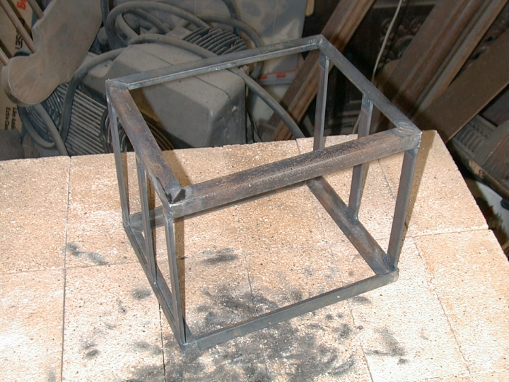
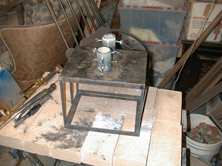
My first step is to build the frame for the box. I first built the top and bottom 9'' x 11'' frames using ¾” x 1/8” angle iron. I then used 6.5-inch long ¾” x 1/8” bar stock for the up rights. Because I already have an oxygen/acetylene welding rig, I decided to use welded construction for the basic frame. If you don't weld, it is possible that you could use rivets or bolts, however that would require a few modifications to my basic plan. The finished box frame looks like this.
Next the forge needs a set of legs to protect what ever it sits on from excess heat build-up. To that end I cut 4 pieces of 3/4"x/1/8" angle iron, 2 1/2" long. These were welded to the base of the frame. Using my 4" right angle grinder, I cleaned up the welds. Then I painted the frame with a coat of high temperature spray paint, to arrest corrosion on any surfaces that will be covered later.
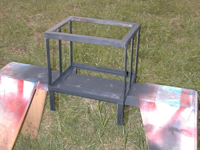
Next my forge needs a top. And on that top, I need some way to hold my forge burners. So I started by cutting a piece of 16-gauge sheet metal to fit the top of my frame. Then I cut two, three-inch long sections of 1 1/2" pipe. This was done by cutting the threads off a 10-inch pipe nipple and then cutting it in half. Each of these was drilled and tapped for six 1/4"x20 thumb screws. These screws will be used to hold and adjust the positions of the burners. Using my burner pair as a guide I marked the sheet metal and position the three-inch pipes. I then welded the pipes to the sheet metal. Once the pipes are in place I burned through the sheet metal with my cutting torch. I then used my die grinder to clean up the chimney holes. The end result of these steps looks like this.
The first photo shows the top resting on the frame before the legs were added. The second photo shows the top pop-riveted into place. The sides and the bottom will be made of a lighter gauge material and also pop-rivet to the frame. The pop-rivets should be protected from the full heat of the forge by the refractory lining. I assembled everything at this point to get a better feel for the finished size.
After attaching the legs I next cut and attached the sheet metal for the sides and the bottom. The sides are attached to the outside of the frame, while the bottom rests inside the frame with only a couple of rivets holding it in place.
With the top, sides and bottom in place, I took a look at the stability of the forge. After factoring in the weight of the doors, I decided to increase the footprint of the forge. With the doors, the forge will be 13 inches from front to back. I decided I wanted the base a little deeper then that. So, I cut two pieces of 3/4-inch square tube stock and welded that on the bottom of the legs, running front to back like skis. After adding the sides, bottom and bases, I once again coated it all with high temperature spray paint, inside and out.
With the body of the forge complete, it is now time to start on the doors. The doors will contain two layers of one-inch thick Kaowool fiber mat. So they are framed with 2 x 1/8 inch angle iron. The doorframes match the ends of the forge box at 8"x11". At each corner inside the frames, I have attached small tabs. These tabs will hold fiber mats in place. I also have added a section of rod sticking out from each door. The rod is to allow me to add a wooden file handle as a door handle. After the welding is complete, the frames are coated with high temperature spray paint. Once again I am painting at this point to prevent corrosion in areas that will be covered latter.
With the welding complete, it is now time to face the doors with sheet metal. Once again I pop-riveted the sheet metal to the frame. I added a 2x2" opening in the rear door and a 2x4" opening in the front. This will allow the forge to breath correctly. It will also allow me an opening for small and medium sized work, with out opening the front door up all the way. The doors are then attached to the frame with 3" hinges and more pop-rivets.
The next step is to address the refractory lining of the forge. The main lining of the forge will be Kaowool. But the floor of the forge will be made of insulating firebrick, to make for a more durable work surface. In order to improve the insulating qualities of the refractory materials and to stabilize the Kaowool, everything will be coated with ITC-100. The firebricks will be coated outside the forge. While the Kaowool will be coated after it is installed.
After that the forge is allowed to dry for a full day. Then it is test fired to finish curing the coating and to burn off any impurities.
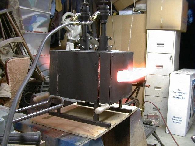
Testing the forge showed I had made an error in the design somewhere. Huge gouts of flame poured out of both the front and rear openings. It appears that two burners move way too much fuel and air for the size of the chamber on my forge. To correct this I am going to attempt two changes. The first will be to tune the burners down, by replacing the gas jet pipe with one having a smaller jet hole. Instead of a number 57 drill I'll use a number 60 drill for the gas jet hole. The second thing I'm going to do is change the gas feed lines to the burners, so that each burner has it's own valve. That way I can try running one burner at a time. At the same time I'm going to rebuild the choke plates to make them large enough to completely close off the top of the burner. That way I can close a burner that is not in use, so it doesn't act like a chimney.
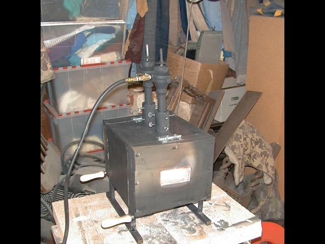
After the tuning changes above the forge produced much less in the way of flames from the openings. However all gas forges still do a fair imitation of a fire-breathing dragon. Basically I was able to reduce the amount of flame by about half. Below are photos of the forge in operation as it is set up now. I had to turn off the flash on the digital camera and steady it on a table to show the flames poring out the openings.
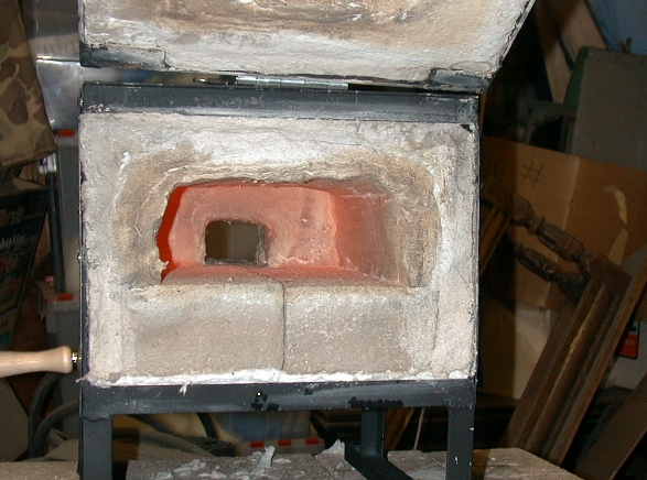
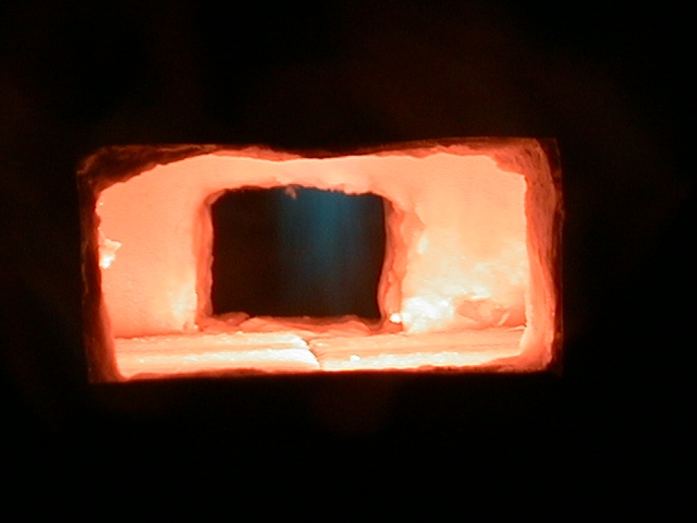
One last shot with the lights turned out and the flash turned off to show the interior of the forge chamber, while the forge was running.
Appendix ‘B’ Bibliography
|
|
|
|
|
|
Pattern-Welded
Blade : Artistry In Iron
by Jim Hrisoulas; Paladin Press;
(December 1994)
New Edge
of the Anvil: A Resource Book for the Blacksmith
by Jack Andrews; Skipjack Pr; 1st
edition (September 1994)
Ron Reil’s Forge and Burner
Design Page; http://www.reil1.net/Forge.shtml
Zoeller Forge II; http://www.geocities.com/zoellerforge/
Appendix ‘C’ Suppliers
Zoeller Forge II; http://www.geocities.com/zoellerforge/
(Burner flares for propane
forge)
Centaur Forge Ltd; http://www.centaurforge.com/
(Blacksmiths tools, mostly for farriers)
Iron Monger Armory; http://www.kingslayer.com/ironmonger/catalog/catalog.htm
(SCA Blacksmith tools)
Admiral Steel; http://www.admiralsteel.com/
(Knife making steels)
Knife and Gun, Inc; http://www.knifeandgun.com/
(All manor of knife making supplies and tools)