
Hagerson Forge, Forge Construction Project
This page last updated on 08/29/2006
One of the things my shop has always lacked is forge. Until now, I have always formed metal using my collection of torches. Then I found Ron Reil's Page about building your own forge and forge burners. At that point I decided I was tired of making do with torches. So the plan is for this page to document the construction of my forge.
Warning
The construction and use of a forge is dangerous. Anyone building a forge based on what I have written here, does so at their own risk. This page is provided for information only and is not to suggest that you build your own forge. This forge is experimental and not a proven design. If you decide to build or use a forge, please make sure you have a complete set of safety equipment for the tools you use. Also please see my shop safety page, where I will list some of the many shop safety rules.
The Overall Plan
The first step was to decide on the size of chamber I needed. This is dictated by the size of the work you want to do. The chamber size dictates the number and size of burners, you will need. Now, most of the work I'm planning on doing is flat and wide. I also plan on doing some knife work at some point. So as a starting point for my forge design, I looked at Master Atar's "nuclear toaster" blade forge, as shown on his video. From there, I decide to widen the forge chamber to handle the large rings I use in my hilt designs. Lastly, I shortened the height of the chamber to keep the total volume down. The resulting chamber size allows me to use two fire bricks as a floor. Overall the end product is going to look like a cross between a blade makers forge and a farriers hot box forge.
Materials List
For the two Forge Burners and Supply Lines
(2) Pre-made Burner Flairs (from Larry Zoeller)
(2) 1 1/2" to 3/4" Reducer Bells (this and the next several items can be found at most plumbing supply outlets)
(2) 3/4"x 8" Pipe Nipples
(2) 1/8"x4" Pipe Nipples
(2) 1/8" Pipe Caps
(1) 1 1/2"x3" Pipe Nipple
(1) 1/8" Pipe "T"
(2) 1/8" Ball Valve
(2) 1/8" 90deg Elbow Fittings
(2) 1.8" 60deg Elbow Fittings
(2) 1/8"x1" Pipe Nipples
(2) 1/8"x1/2" Pipe Nipples
(1) 1/4" to 1/8" Adapter
(1) Propane/Gas Hose
(1) Goss Propane Regulator (found at most welding supply stores)For the Axial Choke Assemblies
(1) 5/16" All Thread Rod (you will need about a 6" length)
(4) 5/16"x3/4" Hex Bolts
(2) 5/16" Lock Washers
(2) 5/16"x1 1/2" Fender Washers
(2) 5/16" Hex Nuts
(2) 5/16" Junction NutsFor the body and forge chamber
(2) Fire Bricks
(10 sq ft) Kaowool Fiber Blanket
(1 pint) ITC 100 Refractory Coating (This and the other two items above can be found at the Clay Art Center)
(2) 3/4x1/8 Angle Iron, 4 feet long
(2) 2x1/8 Angle Iron, 4 feet long
(1) 3/4x1/8 Steel Bar Stock
(1) 1 1/2"x10" Pipe Nipple
(12) 1/4x20x3/4 Thumb Screws
(2) 3 Inch Hinges
(50) 3/16x1/4 Pop-Rivets
(1 sq ft) 16 Gauge Sheet Metal
(5 sq ft) 22 Gauge Sheet Metal
(1) 3/4x1/8 Square Tube Stock, 3 feet long
(2) Cans Zynolite, Black, High Temperature Spray Paint
The Forge Burners
The first step is the construction of the forge burners. I used the EZ Burner plans found on Ron Reil's web site. Using the calculations on Ron's page, I determined I would need two burners to insure my forge can reach a welding heat. For burner construction details please visit Ron's page. I modified the plans slightly, in that I secured the 1/8" pipe that is the gas jet, by using half of a 1 1/2"x3" pipe nipple. First I cut the nipple in half and then screwed the two halves into the backs of the reducing bells, to lock down the 1/8" pipe. By using the 1 1/2" pipe, I allowed for the future addition of an axial choke as shown on Ron's site. The two finished burners were then joined by a "T" fitting. Next a brass ball valve was added. The propane line was attached using a 1/8" to 1/4" adapter. For a propane regulator, I used one made by Goss and purchased from a welding supply store. Below you can see photos of the burners being test fired. The first photo shows the burners running at 4 P.S.I. of propane, the second is at 28 P.S.I. The second photo shows that the direction of the gas jets still needs to be adjusted so that they point straight down the burner tubes.
![]()
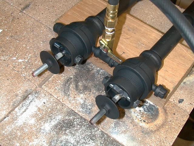
The next step is add a choke. The choke will let me adjust the air flow so as to maintain a clean neutral flame in the forge no matter what gas pressure is used. I decided to use an axial choke based on what I had seen on Ron Reil's page. The choke I built uses elements from an axial choke seen on the site. That choke can be seen here.
First I marked the section of 1 1/2" pipe that locks down the 1/8" gas jet pipe. I marked the 1 1/2" pipe where it lined up with the gas jet pipe. Using these marks, I drilled a pair of holes thru each 1 1/2" section that will run parallel to the gas jet. Next, I cut two 3" sections of the 5/16" all thread. The all thread was then brazed to the junction nuts at a 90 degree angle. Using two 5/16" bolts and one lock washer per burner, the all thread/junction nut assembly is fasten inside the 1 1/2" pipe sections to act as an upright. Last the two 5/15" nuts are brazed onto the fender washers to act as choke plates. These threaded plates are then turned down onto the all thread. Last, the 1 1/2" pipe sections are returned to the their task of locking down the gas jets. Below is a close up of the completed chokes.
The final operation to be performed on the burners is to tune them. Ron Reil has complete tuning instructions on his forge burner FAQ page. To tune my burners, I first increased the gas jet holes from .0400" (#60 drill bit) to .0420" (#58 drill bit) . (Note: after testing the completed forge, I went back and replaced the 1/8" pipe and returned to a .0400" gas jet hole. The why of this will be explained later.) Next, I had to adjust the gas jets to point straight down the burner tubes. Last, I adjusted the burner flair to 1 1/8" of exposure from the end of the 3/4" burner tube.
Building The Forge Box
The forge box is to to built around a solid floor of two fire bricks, two inches tall. Now fire brick is not as good a refectory material as Kaowool. So the fire brick will sit on one inch of Kaowool. I want the forge chamber to be three inches high. The Roof will have two inches of Kaowool. So the total height of forge box will be 8 inches. The box length will match that of the fire bricks at 9 inches. I want a 7 inch wide forge chamber with 2 inches of Kaowool on each side. The means the box will be 11 inches wide. The fire bricks are each 4.5 inches wide, for a total of 9 inches. That means one inch of Kaowool will sit on the fire bricks on each side. The other inch of refractory martial on each side will run down the sides of the fire brick. So the final dimensions for the forge box are 8 inched tall by 11 inches wide by 9 inches long.
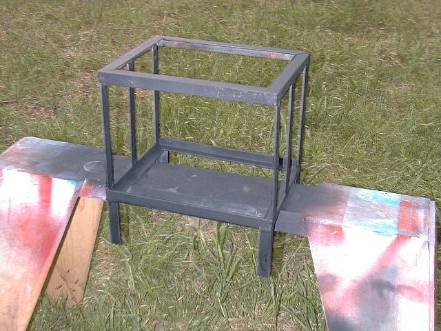
My first step is to build the frame for the box. I first built the top and bottom 9''x11'' frames using 3/4x1/8 angle iron. I then used 6.5 inch long 3/4x1/8 bar stock for the up rights. Because I already have an oxygen/acetylene welding rig, I decided to use welded construction for the basic frame. If you don't weld, it is possible that you could use rivets or bolts, however that would require a few modifications to my basic plan. The finished box frame looks like this.

Next the forge needs a set of legs to protect what ever it sits on from excess heat build-up. To that end I cut 4 pieces of 3/4"x/1/8" angle iron, 2 1/2" long. These were welded to the base of the frame. Using my 4" right angle grinder, I cleaned up the welds. Then I painted the frame with a coat of high temperature spray paint, to arrest corrosion on any surfaces that will be covered later.
Next my forge needs a top. And on that top, I need some way to hold my forge burners. So I started by cutting a piece of 16 gauge sheet metal to fit the top of my frame. Then I cut two, three inch long sections of 1 1/2" pipe. This was done by cutting the threads off a 10 inch pipe nipple and then cutting it in half. Each of these was drilled and tapped for six 1/4"x20 thumb screws. These screws will be used to hold and adjust the positions of the burners. Using my burner pair as a guide I marked the sheet metal and position the three inch pipes. I then welded the pipes to the sheet metal. Once the pipes are in place I burned through the sheet metal with my cutting torch. I then used my die grinder to clean up the chimney holes. The end result of these steps looks like this.
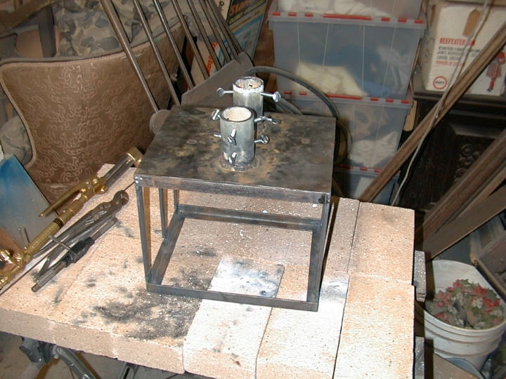
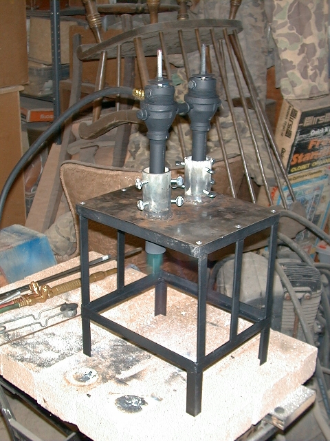
The first photo shows the top resting on the frame before the legs were added. The second photo shows the top pop-riveted into place. The sides and the bottom will be made of a lighter gauge material and also pop-rivet to the frame. The pop-rivets should be protected from the full heat of the forge by the refractory lining. I assembled everything at this point to get a better feel for the finished size.
After attaching the legs I next cut and attached the sheet metal for the sides and the bottom. The sides are attached to the outside of the frame, while the bottom rests inside the frame with only a couple of rivets holding it in place.
With the top, sides and bottom in place, I took a look at the stability of the forge. After factoring in the weight of the doors, I decided to increase the foot print of the forge. With the doors, the forge will be 13 inches from front to back. I decided I wanted the base a little deeper then that. So, I cut two pieces of 3/4 inch square tube stock and welded that on the bottom of the legs, running front to back like skis. After adding the sides, bottom and bases, I once again coated it all with high temperature spray paint, inside and out.
With the body of the forge complete, it is now time to start on the doors. The doors will contain two layers of one inch thick Kaowool fiber mat. So they are framed with 2 x 1/8 inch angle iron. The door frames match the ends of the forge box at 8"x11". At each corner inside the frames, I have attached small tabs. These tabs will hold fiber mats in place. I also have added a section of rod sticking out from each door. The rod is to allow me to add a wooden file handle as a door handle. After the welding is complete, the frames are coated with high temperature spray paint. Once again I am painting at this point to prevent corrosion in areas that will be covered latter.
With the welding complete, its time to face the doors with sheet metal. Once again I pop-riveted the sheet metal to the frame. I added a 2x2" opening in the rear door and a 2x4" opening in the front. This will allow the forge to breath correctly. It will also allow me an opening for small and medium sized work, with out opening the front door up all the way. The doors are then attached to the frame with 3" hinges and more pop-rivets.
The next step is to address the refractory lining of the forge. The main lining of the forge will be Kaowool. But the floor of the forge will be made of insulating fire brick, to make for a more durable work surface. In order to improve the insulating qualities of the refractory materials and to stabilize the Kaowool, everything will be coated with ITC-100. The fire bricks will be coated outside the forge. While the Kaowool will be coated after it is installed.
After that the forge is allowed to dry. Then it is test fired to finish curing the coating and to burn off any impurities.
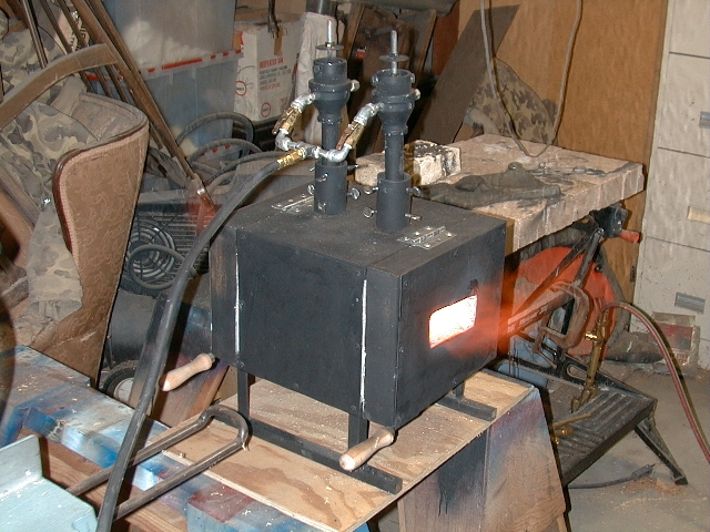
Testing the forge showed I had made an error in the design somewhere. Huge gouts of flame poured out of both the front and rear openings. It appears that two burners move way too much fuel and air for the size of the chamber on my forge. To correct this I am going to attempt two changes. The first will be to tune the burners down, by replacing the gas jet pipe with one having a smaller jet hole. Instead of t a number 57 drill, I'll use a number 60 drill for the gas jet hole. The second thing I'm going to do is change the gas feed lines to the burners, so that each burner has it's own valve. That way I can try running one burner at a time. At the same time I'm going to rebuild the choke plates to make them large enough to completely close off the top of the burner. That way I can close a burner that is not in use, so it doesn't act like a chimney.
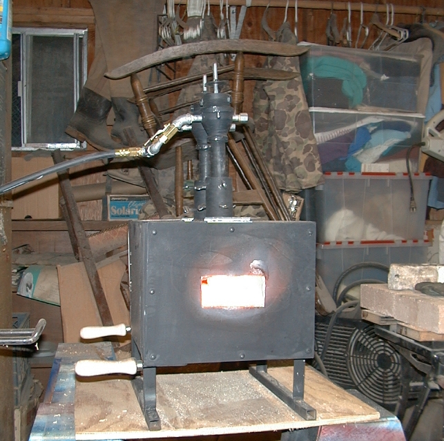
After the tuning changes above the forge produced much less in the way of flames from the openings. However all gas forges still do a fair imitation of a fire breathing dragon. Basically I was able to reduce the amount of flame by about half. Below are photos of the forge in operation as it is set up now. I had to turn off the flash on the digital camera and steady it on a table to show the flames poring out the openings.

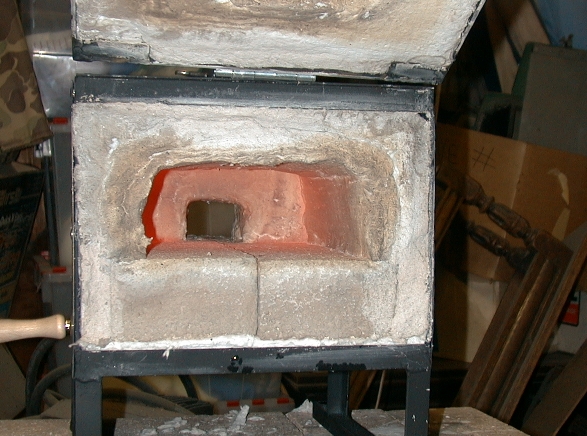
One last shot with the lights turned out and the flash turned off to show the interior of the forge chamber, while the forge was running.

For More Information Contact the Author via e-mail.